ATTENTION: We recommend you DO NOT DISASSEMBLE or ATTEMPT TO REPAIR OR
REPLACE ANY PARTS ON ANY ELECTRONIC / ELECTRICAL DEVICE without proper,
technical training and repairs / modifications should always be left to
qualified technicians.
"WARNING: PLEASE
USE CAUTION WITH ANY ELECTRICAL DEVICE. ANY REPAIR AND / OR RESTORATION
SHOULD BE UNDERTAKEN ONLY BY A QUALIFIED TECHNICIAN. DO NOT OPEN OR ATTEMPT
TO REPAIR ANY ELECTRONIC DEVICE WITHOUT PROPER INSTRUCTION, EXPERIENCE,
BACKGROUND, TRAINING OR KNOWLEDGE, OR TAKING PROPER SAFETY PRECAUTIONS.
THERE ARE NO 'USER SERVICEABLE' PARTS, SYSTEMS OR CIRCUITS INSIDE.
POTENTIALLY HARMFUL, INJURIOUS AND / OR LETHAL ELECTRIC VOLTAGE AND CURRENT
INSIDE.
IT CAN KILL YOU AND WILL HURT THE ENTIRE TIME YOU ARE DYING."
The following information is for
'entertainment value' ONLY and not intended as 'how to' / DIY instructions,
and by NO MEANS is it instruction on how to repair, nor intended as
incentive nor encouragement to tackle any electronic repairs yourself!
|
We will be adding MANY notes / info as we go
thru old 'work sheets', as time allows
and repairs are completed...
|
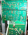
a/d/s L910 Speakers.
Issue: LED "Level / Power Meters' intermittent / dim...
Solution that worked for us in this case: We discovered compromised /
fatigued 'legs' on the first and second LED's. The first LED appeared to
have been 're-flowed' with solder at some time. The 'second up' LED had one
leg 'severed' by fatigue, but was intermittently making connection, which
then allowed the remainder of the LED's to fire at full brightness. We added
a short section of wire as a 'scab' (soldered on the full length) to
'bridge' the fatigued section. We re-flowed a few others proactively, and
inspected the meters in the other as well.
|
a/d/s L910 Speakers.
Issue: Extraneous 'rattles' from crossover assembly...
Solution that worked for us in this case: While there had been a bit of
'hot glue' applied at the factory, it was insufficient to squelch all the
'rattles' that showed up on our AF generator sweep. Adding hot glue to the
components to secure / 'pad' them to each other and /or the circuit board
eliminated the rattles (don't forget the 'wire' clip that holds the LED
meter circuit card perpendicular to the main circuit board. Simply 'coat' it
with hot glue and put glue between it and the LED circuit board junction).
|
Akai GX-60R Cassette Deck.
Issue: Transport switches 'randomly' from forward to reverse...
Solution that worked for us in this case: The transport
buttons must be completely 'free' in their openings of the front bezel,
with no 'side' pressure. There is a mounting plate behind the face
plate, and it as well as the face plate, must be aligned 'perfectly'
with no 'side pressure' on the switches. Once aligned, fasteners should
hold everything in position. If the face plate shifts, relative to the
chassis (such as in shipping / transit), the transport can 'mis-behave'
again.
|
Akai "4000" series (GX-4000
etc).
Issue: When fast winding we were
experiencing the tape 'wandering' off the pinch roller surface and
getting trapped between the inside edge of the pinch roller and the face
plate during some point in the process...
Solution that worked for us in this case: This is almost always,
and was due to a lack of 'back
tension' on the supply reel. There is no mechanism in this series of
decks to apply tension, but adding some 500,000 Silicon lube to it's
axles and bushings applied enough tension to the supply reels that it
solved the issue.
|
Akai
1700 & 1710 (and maybe other 1700 series).
Issue: Deck not erasing properly...
Solution that worked for us in this case: While there could be a number of reasons for
this, an interesting one we came across was that the adjustable core /
slug in the oscillating coil (17-L1) had backed out almost to the point
of falling completely out due to gravity and vibrations over time. Once
screwed back in (should be adjusted properly, but approx 4mm below the
outside rim of the coil body as a starting point) and once adjusted
properly, maybe secured with a bit of nail polish.
|
Akai
1700 & 1710 (and maybe other 1700 series).
Issue: Deck intermittently / randomly not recording at all or
recording low on one or both channels...
Solution that worked for us in this case: We recently had a
"1710" that we restored that once on our 'burn / final inspection' bench
was not recording on the left channel. We had no signal at the level
meter as well. It would play back from both channels, but recording was
non-existent on the 'left' channel. We traced it to a corroded / dirty
contact on the 'normally closed' "MIC" jack. Once we burnished the
contacts on the 'switched' portion of the jack, the signal was back to
full strength throughout the food chain.
|
Akai
1700 & 1710 (and maybe other 1700 series).
Issue: Excessive 60Hz hum from one or both sides...
Solution that worked for us in this case: While this could be a faulty
electrolytic capacitor (most likely firstly assumed culprit), bad ground
(second most likely culprit), etc. we found one that had VERY loud 60Hz
hum on one channel to be the fault of one of the RCA connectors on the
inside chassis that connects the heads to the rest of the circuitry.
Connectors needed to be cleaned / re-sprung. That completely cleared up
the hum.
|
Akai
1730-SS (and maybe others).
Issue: Excessive noise / hash / static throughout audio on
playback and recording.
Solution that worked for us in this case: This deck is fairly
easy to service as far as the audio boards go. As it's a quadraphonic
capable deck, there are 2x 'two channel' playback circuit boards and 2x
'two channel' Record circuit boards, that are installed with edge cards,
and are located on the bottom of the unit (just turn on it's side to
access them). ALL four of them had 'black leg' on ALL transistors. They
were 2SC458 & 2SC871 transistors that we almost always see 'black leg'
on. There were 4 on each board. We also determined that the Sanyo LD-3141
/ LD3141 IC's (Integrated circuits) had issues, so we salvaged some from a donor deck we
had. Changing all of those components allowed us to get the deck
adjusted to satisfactory levels (it actually sounded awesome on playback
of some of our best tapes). It could probably benefit from further
changing of all the electrolytic caps, but that would be a massive
undertaking that would raise the end price out the realm of 'monetary
practicality').
|
Akai X-1800SD (THREE TYPES:
A-Type, B-Type & C-Type).
Issue: There were three different versions (internally) of the Akai X-1800SD
Reel to reel / 8-track cartridge tape deck. Some of the circuit boards
are interchangeable from A-Type to B-Type or B-Type to C-Type, but never
from A-Type to C-Type. Other parts such as some of the cosmetic parts,
tape counters & output transistors will vary as well. The "Type-C" has a PB/REC amp (lower section) that is MUCH easier to work on from an aspect
of cleaning the controls, and adjusting the internal levels. Also, some
of the parts are interchangeable with the Akai X-1810 (very similar deck
both externally and internally. The Type-C and the X-1810 both utilize
the same amplifier output transistors; 2SC1060 X 4)
Other various differences in the Types A, B & C;
Type-A has a 'large' bezel on the tape counter that is 'convex' to the
front panel, and requires a larger opening in the face panel.
Type-C features the addition of a selector for 'Auto-Stop' or
'Continuous Play' for the 8-Track cartridge. Switch is located near the
'cartridge insert' opening on the side.
|
Akai X-1800SD.
Issue: We had one that had one of the VU level meters exhibiting a reduced
level by about 12 dB...
Solution that worked for us in this case: There's not separate 'meter level' adjustment
built into the deck so nothing to do there. We substituted 2 other of
the same / OEM meters in it's place with the same results. The actual
Input and Output level was showing the same on our mV meter and our dual
track O-scope so we knew it was isolated to the meter. We isolated the
section on the schematic and found the circuit was a capacitor, 2x
diodes and 2x resistors. The Diodes checked fine as did the resistors.
We had another 'non-polar', 25V / 3.3mF cap of the same value in stock
and once it was replaced, the meter worked perfectly in unison with the
other.
|
X-1800SD & X-1810 Random Notes:
TYPE-C 1800 - Can use ‘cheater extension’ cable we
(Oak Tree Vintage) made from X-1810 series.
1800 VS 1810
Single motor vs 3 Motor
Rubber Stoppers vs Spindle Locks
No Auto-Rev vs Auto-Reverse
Without ‘cheater cables’ the deck is fairly difficult to service as the
‘pre-amp’ and transport are separated, but in order to record, need to
be ‘mechanically’ coupled, and their umbilical’s are long enough.
There’s possible work arounds for those, that are easier on the Type-C
and 1810 than the type-A and B.
As long as the ‘cam dogs’ are in decent shape, with only ‘minimal’
cracks (depends on where the cracks are and what measures can be taken
to stabilize them), the transport is actually a fairly durable design.
There’s not really any ‘finicky’ mechanisms that won’t be overcome by
the robust transport actions.
The rubber idler tires seem to have ALL aged well. We don’t often see
them with issues, and typically still have adequate traction, especially
once resurfaced / reconditioned.
X-1810D is much easier to service as there’s no ‘amp gubbins’ to get in
the way.
Entire 8-Track deck assembly completely removes for service. Easier
fasteners as well (sheet metal screws vs bolts with tiny nuts)
|
Akai X-1810.
Issue: We had one very intermittent auto-reverse on at least one (actually most
all of them will exhibit some sort of intermittency with their
Auto-Reverse at this point, 45+ years on)...
Solution that worked for us in this case: The 'manual reverse /
direction change' switches will certainly need to be disassembled and
cleaned (silver plated), but there are other possible causes. One needed
the associated relay dismantled and it's contacts burnished (we actually
do that on all of them now). There's also a Hitachi transistor,
"2SC458", that is know for developing 'black legs' that compromise
internal device integrity typically leading to noise, intermittency or
complete failure and should usually be changed. The last one we had
the issue with we couldn't solve the issue till after changing all the
transistors on the board (which didn't improve it so we changed them
back to the originals). We finally deduced that the issue was an
intermittent, reed / micro-switch in the 8-Track cartridge slot that is
there to prevent someone manually changing directions with an 8-Track
tape inserted or a reel tape being left in play (while the 8-track
cartridge is playing) and it 'auto-reversing' due to sensing tape being
installed. We couldn't really disassemble the switch for repair, and
didn't have any direct replacements immediately in stock, nor other
'parts' X-1810's' at the time, but we did figure out that the same
switch is used for a slightly different purpose in the Akai X-1800 (at
least the C-Type) and we had one or two of those for parts. Changing the
switch solved the problem, but we still changed out the 'black legged'
Hitachi 2SC458 transistor.
|
Califone 1430C VS 1430K.
Issue: Not so much an issue, as a "Note of Interest". The later
model Califone 1430C version utilized a small, DC powered drive motor,
vs the Califone 1430K (and pretty much every other earlier model) that
was powered by the more standard, Shaded Pole AC motor. There was a much
earlier 1430C, but we're not sure which motor it utilized.
|
Cerwin Vega RE-30 (and
probably RE-20, RE-25, RE-38, D / DX series and many other speaker by
Cerwin Vega or any manufacturer.
Issue: Sympathetic vibration of cabinet rear panel, baffle board
or sides between 80Hz up to about 200Hz or so when tested with a sine
wave / function generator. The design of this speaker has braces going
from the baffle board to the rear panel and from each side to reduce
cabinet resonance (rightfully so and a great idea {when done properly}).
The issue is that the braces (particle board strips that are approx .75"
x 1.5" on the ends) are simply 'butted up against' the cabinet walls and
were originally attached with 'hot glue' (and not even around their
entire perimeter). They did all of the securing internally, but
'technically' it would have been a good idea to have screwed them in
from the outside AND put wood glue on the 'brace end to panel' junctions
as well. The issue with that is 'visible fasteners' and wood glue takes
too long to dry in the manufacturing process. 20-40 years later, hot
glue looses it's 'fastening ability' and the ends of the braces are free
to rattle and vibrate against not only the cabinet walls, but the
residual hot glue as well. Barring adding external fasteners, the most
practical way to address this is to flow some wood glue between the end
of the brace and the panel. Not the 'best' way to address it, but will
work fine, likely for many decades. If you don't care about the external
cosmetics, or can utilize a technique to hide the fastener heads
acceptably, you can also use a couple fasteners in the the brace ends
with glue (be sure and pre-drill first so as to not split out the
particle board braces). If you really want to do this the most correct
way, all of the braces should be removed, all of the residual hot-glue
scraped off, and then proceed with the above processes.
|
EV / Tapco 100M Entertainer
Powered Mixer / PA Console Board etc.
Issue: This was one of the most successful electronic units ever made by
anybody, evidenced by it's VERY long run. There do appear to have been
varying iterations of this model, not simply distinguished by being badged either "Tapco" or "EV". There's too much random information to
include here, so for the 'rest of the story',
Click Here...
|
FOSTEX MODEL 80.
Notes: There are 2x 'square' belts on each reel motor and 1x 'flat' belt for
the capstan for a total of 5 belts. They are fairly difficult to source
and relatively expensive.
|
FOSTEX MODEL
E16, B16, Model 80, Model 20, R8 and possibly
other that utilize LED's for metering.
Notes: Fostex utilized very small (actually microscopic) LED's in
the level meters of many of their models. It is very common that a
Fostex unit with LED metering will have a number of segments out. Our
experience is that it is not any sort of 'drive' circuit or compromised
solder joints, but bad LED's. The originals are not very visible with
the naked eye. The issue with them will typically be that while they are
attached to the circuit board directly on one side, the other "up
facing" side has a "thinner than a hair" wire attached to the actual
"top" of the led. Looking thru a microscope the wire appears to be made
of gold. The entire LED and lead are further coated in silicone. The
wire attached to the top of many of them will be detached. It is VERY
fragile. Even a fine artist brush would break the connection. They do
not seem to be practically repairable (we tried while the circuit board
was under our Nikon Stereo microscope). The only 'fix" we could find was
a shop in California called "Quad City Electronics" in Newhall
California that would replace them with new, more robustly attached
LED's. Once that operation was done, they worked again
perfectly.
|
GAF
8MM Film Projectors, such as; 2588, Wards 811, etc.
Issue: These projectors are quite 'Rube Goldbery' inside......
Solution that worked for us in this case: There's a lot of
wheels, pulleys, Figure-8 twisted belts, and combinations of 'turning /
spinning' things, moving in all kinds of directions, many of which
depend on minute adjustments one direction or another to run correctly.
One such mechanism that is particularly critical to running correctly,
is immediately off the motor. Most of this series have a fairly small,
but thick "O-Ring" that goes from the motor pulley, to the first
'Aluminum' pulley that also drives the Tilton 'Rubberized Cloth' belt
and another, larger o-ring. One issue is that the projector can start
off running slow, then speed up, then slow down again. Or, the motor can
'jam' up completely and stop running (or all of those things). When
replacing the first 'drive' belt, it's overall length is critically
important. Also, the aluminum, 'combination' pulley (about 1" in
diameter), will need to be removed, have it's bushing cleaned and
re-lubed (30wt oil works great instead of 'fine machine' oil on that
one). There's an 1/4 head screw to adjust the 'transmission' (you'll
likely need a service manual to identify the "transmission") and there's
like a VERY SMALL 'sweet spot' along it's adjusting slot where all of
the functions will work reliably (will likely be trial and error to get
it working correctly each and every time and over time). Even once all
of that is done, there may be the occasional time that a belt 'jumps'
off a pulley, and functions such as Fast Forward and Re-Wind may still
be sluggish (use your finger to 'help' them along), especially with the
film still threaded thru the film track (although the 'Fast Wind' issues
are not related to any of the mechanism mentioned above, they're just
common).
|
KENWOOD BASIC C2 PRE-AMP
Issue: While the Basic C2 is a good
sounding pre-amp, chocked full of features, it does have a couple of
issues. Both are due to the utilization of very 'fragile / anemic'
potentiometers to control balance and headphone level.
1)
Balance Control Issue. This usually manifests itself by having one
channel being dropped out. I suppose you could have both channels out.
Generally one or two channels 'down' would not be indicative of an issue
with the "balance control", except with the Kenwood C2.
Unfortunately, there does not seem to be, at least of this writing, a
direct replacement for this potentiometer. There are a couple of 'photo
essay' / writings out there on the web about re-building the pot, but
this is 'micro-surgery' and the potentiometer is not meant to be taken
apart. As most folks will never move the balance control from 'dead
center' you can simply use two small 'jumpers' to bridge across the pot
(obviously you'll need to deduce which solder joints to jumper, and we
haven't taken photos yet of our process to post). There is one page that
writes extensively about substituting 180k resistors, but not sure why
that's being instructed as the pot is in a "zero Ohms" position when
each channel is on at full volume (control centered), and only at the
180k on the side that is 'balanced away from'. For us, the jumpers work
perfectly.
.JPG)
.JPG)
2) Headphone Control Issue.
Again, 'crappy' potentiometer. Again, jumpers took care of this issue.
The volume still follows the 'main volume' control anyway. What the
separate level control would allow you to do is attenuate it down from
the main volume level. Not sure that this would ever be used in a 'real
world' situation, so seems like an 'excusable' workaround as well....We
did have one unit that not only had a bad level pot, but also had 2-3
extra 'cloned' signals riding on the main signal on one channel. We
traced it to the headphone level board. As the 'headphone' amp is a
fairly 'fringe' feature, we didn't pursue it far enough to rectify.
Sorry.
|
KENWOOD KA-6000.
Issue: Unit exhibited
a slow (about 2 per second) 'pulsing' of woofers from both sides once
'warmed up' (we had to get if fairly hot before it would have the issue.
In fact, with it's sheet metal cover off it wouldn't get hot enough, so
we had to utilize a heat gun to warm up the transistors alternating with
'freeze spray' to determine which transistor was causing
the issue). We discovered that it was one of the Hitachi "2SC458" transistors on
the driver board that was causing the pulsing (and it was exhibiting a
symptom called 'black legs' which is pretty well known to be an issue
with most Hitachi 2SC458 transistors out there). Even though it was an
issue on one channel, it did the same pulsing from both sides into any
speakers' woofer that was connected (probably pulling on the power
supply hard enough to effect the other side, but we didn't investigate
that). Just replaced ALL the 2SC458's as well as all the 2SC871
transistors (which also had black legs) with new, KSC1815 transistors
and NTE85's,
and the problem was fixed (pretty much all the TO-92 cased / epoxy
transistors were exhibiting a symptom called 'black legs' . We then warmed it back up with the heat gun,
and it would not 'pulse' anymore. Yea!
|
KENWOOD
KR-77 receiver (but same could be applicable to
hundreds of units).
Issue: Unit would cut on and off after extensive warm-up (about
an hour) at above average volumes...
Solution that worked for us in this case: We narrowed it down to
a Hitachi 2SC458 transistor in the protection circuit as the issue by using 'freeze spray' alternating with a heat
gun / soldering iron as the culprit (YES, of course, it had "black legs /
leads"). The transistor that would improve
with freeze spray and cut off when warmed with heat gun or soldering iron.
We replaced it with an NTE-85 and problem solved. We changed out the other
pair of black legged, Hitachi 2SC458 transistors on the amplifier board as
well.
|
KENWOOD
KR-4200 receiver.
Issue: Unit exhibited 60Hz hum in R channel and excessive
'hiss' on the L channel. While the hiss remained constant, hum would
increase slightly after a few minutes of warm-up...
Solution that worked for us in this case: We narrowed it down to one
of the 2SC1345 transistors by using 'freeze spray' alternating with a heat
gun as the culprit. The transistor that would allow the 'hum' and would improve
with freeze spray, until it got too cold, then would start to hiss as well,
then when chilled further would cease to function until it warmed. The L
channel would simply 'improve' when chilled. We verified these transistors
as the culprits by 'swapping' them. The symptoms then switched channels.
(prior to those tests, we had checked EVERY electrolytic in the power supply
and driver boards to no avail). Replaced both 2SC1345 transistors and
noise problem solved. Next issue was then that the DC was creeping up and
triggering the DC Protection Relay to as high as 3 Volts! Changing the other
pair of 2SC1345 transistors in the signal chain rectified that.
|
KENWOOD KR-9940
/ 9340 quad receiver and Other Kenwoods.
1) Speaker 'B' will not function unless you already have
'Speaker-A' loaded.
2) Power switch on the Kenwood KR-9940 is interesting.
It's a 'push' button, with a neon lamp inside that act's as a kind of 'night
light' / 'locate it in the dark' light. The neon light is 'ON' when the unit
is OFF and visa-versa. It's identified as an 'R13-21' and while there are
references out there on the web, it does not appear as 'obtainable' for
replacement. We managed to 'rebuild' one (not generally what you're supposed
to do). There's a 'tapered plunger on a spring internally. The switch was
intermittent. We found that the 'base / flange' on the plastic plunger was
worn 'crooked', so we used a file to even it out (thus making it thinner)
and added a small shim to make up the difference (assuming it needed the
extra thickness). Once re-assembled, the switch was no longer intermittent
and functioned ON and OFF as it should.
|
KENWOOD KR-NINE-G, 9000, 10000,
ELEVEN-G etc.
This series of Kenwood receivers offered a 'Timer'
function / feature to function as a 'sleep timer'. It is essentially a
standard clock works / 'kitchen' timer mechanism. It operated from a knob on
the front panel on the left end of the unit. The knob extended to an
aluminum shaft. The 'timer' body also had an aluminum shaft protruding. The
two aluminum shafts met at a 'center point' and were coupled with a plastic
or nylon sleeve with 2 to 4 set screws. The knob takes a fair amount of
effort to turn the clock works, as you're at a mechanical 'dis-advantage'
due to the clock gearing. Typically the 35+ year old plastic sleeve cannot
withstand that type of force anymore and cracks, rendering not only the
timer useless, but if the unit did not end up in the 'Reset' position,
useless as well. The 'work-around' is to put the unit in it's 'Reset'
position and then disengage the locking sleeve so it can't be put back into
'timer' mode. If the sleeve is already cracked or broken (and it likely will
be) use a pair of pliers to rotate the rear most aluminum shaft, put the
unit into it's 'Reset' position and loosen the set screws. We do this to all
of this series, whether the timer still functions or not, as it's not a
matter of 'if' it will break, but 'when'.
|
|
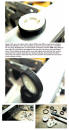
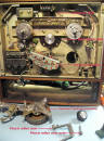
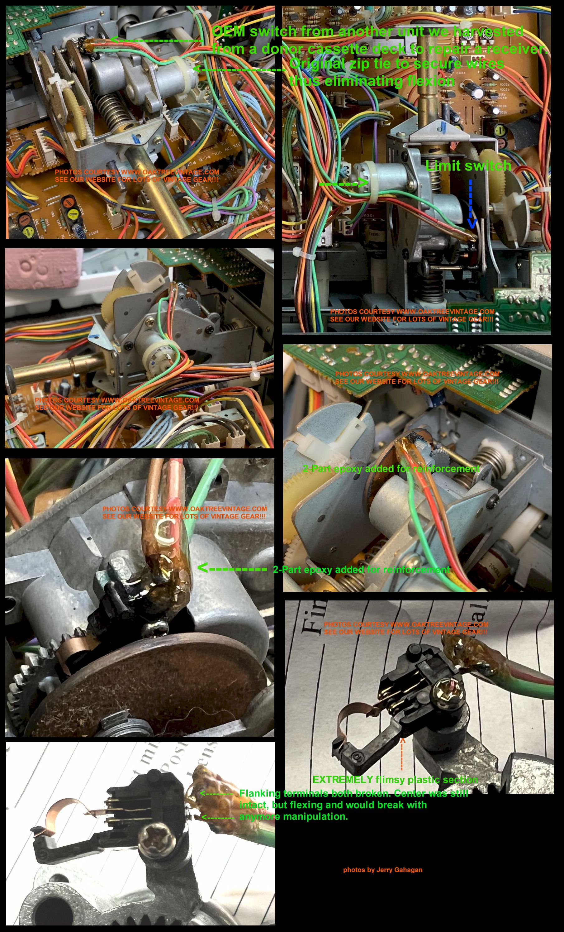
Luxman "suck-face"
Receivers and Cassette Decks (Such as Luxman receivers RX-101, RX-102,
RX-103, KX-101, KX-102, KX-103 Cassette Decks and possibly others.)
Issue:
Just a couple of notes about working on these servo
systems that retract the face section (suckface) on these units. There's
an EXTREMELY FRAGILE double throw / single pole limit switch that
controls voltage to the retract motor. There are three wires (red, green
and brown) going to it that has a bit of glue holding them together and
in place over their solder joints so they're not subject to vibration /
manipulation. It's NOT enough. The wires are soldered to tabs that are
simply continuations of the thin switch contacts / reeds. Those wires
are then held fast to the motor by a zip tie to eliminate stress on the
attachment points of those wires and the switch. The entire affair is
EXTREMELY flimsy and proprietary. If you break one of those contacts
near the solder joints, it will VERY DIFFICULT to execute a repair or to
fabricate any replacement solutions. The plastic parts are also
incredibly anemic. In servicing that mechanism on one of the handful
we've done, two of the solder tabs broke away, leaving only the center.
We looked at fabricating new solder points, but that probably would have
taken a couple hours, and likely would not have worked. Fortunately we
had a working parts unit to swap the switch from. Bottom line is BE
CAREFUL working on one of these. One thing to do is what we did in that
we took some 2-part epoxy and built up around the glue that's already on
the wires / terminals, and tied that better to the plastic portion of
the switch. Even then, you have to be careful handling those wires /
switch as any manipulation will put stress on those reed parts that are
soldered to the wires.

We didn't do an extensive search for that micro-switch (since we had one
from a working unit), but if any of you know of a replacement,
please let us know.
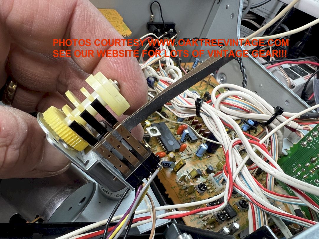
Also, regarding the belt that drives the suck-face mechanism. There a
belt that is buried in the 'transmission' of that mechanism that will
likely need to be replaced. They did not design in very much clearance
between the pot metal housing for the belt pulleys so the belt has to be
VERY thin, or it will rub on the inside of the housing. More room inside
the housing would have allowed for a more substantial belt btw.
I don't think they ever thought anyone would be needing to service this
mechanism. A couple of VERY MINOR design changes originally would have
made this a much more durable mechanism (along with making the belt
'external' to the transmission housing so you don't have to disassemble
it to the degree you need to just to change the belt!!!).
|
|
Marantz 5220 Cassette Deck
(likely also applicable to Marantz 5020, 5120, 5200, 5400, 5420
and possibly others.
Issue:
Excessive WOW / Flutter. We've found that the 'belt
kits' sold by some ebay sellers are 'wrong' for this deck. While it is
perfectly permissible to utilize 'round' belts in many tape decks, it is
NOT permissible in the Marantz 5220. You MUST use 'SQUARE' belts. The
only reason we can deduce is that the round belt cyclically 'rode' up on
the edges of the 'idler' pulley, causing the anomaly.
|
|
Marshall JCM-800 Guitar amp head
Issue:
Marshall JCM800 was blowing the 'HT' fuse (it's been a
while, but I believe it was the 'heater' fuse. Could have been the main)
when level was raised much above about '9 o'clock' on the 'Master' volume
unless output tubes #1 and #2 were removed...
Solution that worked for us in this case:
There was evidence of 'arching'
between pins #1 & #2 on the first output tube. It had the issue when we
acquired it, and from the 'carbon track' burned into the 'bakelite' tube
socket, it looked like it had been going on for quite some time. We tried
removing the carbon track with a wire brush, but while it did allow the
volume to be increased some, it still arc'd and would blow the fuse. We
ordered some ceramic tube sockets, and replaced the bad one (need to do them
all some day, but it's a 'bit of a job'). No more issues, and we can now
'crank it to Eleven'! Just FYI, the AC current draw at idle on our Marshall
JCM-800 without the tubes was .05A and with the tube installed = .43A in
'Standby' mode and 1.1A with 'Standby' off.
|
|
MCS / TECHNICS / HITACHI Belt Drive Turntable Motor restoration
Page Link
|
|
Nakamichi BX-1 & BX-125
cassette tape deck making (and probably others)
Rhythmic clicking / ticking / static noise.
Issue: We have both of these decks. We first noticed the issue of a fairly
faint, 'ticking noise' that was cyclical / rhythmic via the audio
outputs. It did vary with the rpm's of the motor...
Solution that worked for us in this case: We swapped the
transports from the Nakamichi BX-125 to the BX-1 (their identical except
for the labeling on one of the motors). Swapping them made no
difference. We did notice that if we took a piece of wire (first used a
small screwdriver) and grounded the capstan drive motor shaft to ground,
the ticking resolved. They only make the sound with a tape loaded and in
'PLAY'. The decks will go into "PLAY" without a tape loaded and will not
exhibit the clicking noise then. They also will not make it if we load
and engage "PLAY" with an tape with an 'empty' shell. It seems to be
related to 'static build-up / discharge', but so far we haven't found a
solution. We could 'add' a piece of 'spring' from ground to the motor
shaft (has multiple, potential, future issues). We tried grounding
different points on the transport (it's actually already grounded) and
from the PB/REC head case to ground (although that should be a
completely isolated shell and SHOULDN'T affect it...which it didn't) to
no avail. I don't know if I mentioned it, but both have their original "Nakamichi"
#BFA2L36 motors installed.
Any advice / further info welcome.
NEW INFO 5/5/20;
In messing around with different 'ground points' (even grounding the
brass, motor pulley to ground) we were able to hear 'differences' in the
amount of clicking / ticking, but not able to practically address it
(temporarily touching a screwdriver to the spinning, brass motor pulley
to ground seemed to eliminate it, but not practical for the long
term obviously). We swapped the transports from a Nakamich BX-1 to a
BX-125 (they're almost identical decks internally) would change things 'willy
nilly', but nothing address it satisfactorily UNTIL...
the tech burnished / roughed up / scraped the zinc coated chassis parts
where the 'ground wire' connects the transport assembly to the chassis,
and 'torque'd' the screws down well and
voilŕ, CLICKING / TICKING
NOISE PROBLEM SOLVED.
We read a few other 'theories' out there on the web and were even
thinking some sort of 'filter capacitors' as well, but it was simply
'compromised grounds' (which is often the culprit in electronics).
|
Nakamichi CR-3A (and likely
others)
cassette tape deck plastic can react with "CRC Contact Cleaner 2000".
We just experienced all of the plastic push buttons melting / welding to
the face panel. First issue we've had with "CRC Contact Cleaner 2000".
'After the fact' we sprayed a bit on an out of the way area of the face
panel, and sure enough, the plastic softened and you could leave a
finger print in it.
|
Nakamichi RX-202 (and likely
others such as AND including Nakamichi Cassette Deck 1, 1.5, 2,
Nakamichi BX series: BX-1, BX-2, BX-100, BX-125, BX-150, BX-300,
Nakamichi CR series: CR-1, CR-2, CR-3, CR-4, CR-5, CR-7. CR-40 Nakamichi
MR series: MR-1, MR-2, Nakamichi RX series: RX-202, Nakamichi ZX-5,
Nakamichi DR-1, DR-2, DR-3, DR-5, DR-8, DR-10, Onkyo TA-2600, TA-2700
cassette tape decks).
Issue: Following
10 hours of bench work, the deck exhibited intermittent transport
function and / or transport won't move in Play, FF or REW and sometimes
will simply cycle between the "Stop", "Play" and "Pause" LEDs for a few
seconds at a time....
Solution that worked for us in this case: We did a bit of
research on this issue and saw a lot of other examples of folks having
the same issue. We also read that the general consensus was that the
problem was due to issues with the "Mode" reed switches (#OC80027A) and
/ or the "Control" / "Cam" motor (#VA700B04). The opinion was that the
brushes had a build up of carbon. Some folks were trying a technique of
connecting 12V directly to the motor and simply running it for a while
to knock some of the carbon off the commutators and brushes. While that
could be a 'temporary' fix, I needed this unit to be good for the long
haul. I still wasn't convinced that the issue was due to the 'reed
switches' (there's three on a mounting under a triple-lobed cam) or the
motor. We removed the motor (#VA700B04) / cam (#OC80026A) / switch
assembly (#OC80027A) and disassembled one from the other. We
connected 12V to the motor and it ran. Just as an exercise, we then
reversed the polarity to run the motor backwards to really 'knock' off
any carbon. After a few seconds, the motor started slowing down.
Previously the motor would still run well at 6, 7.5 & 9V, but not it
would only really run at 12V and then it was still slower. We had to
open the motor at that point. I expected to see the gaps in the
commutator plates clogged up with carbon, but they were clear. With a
jewelers loop, we could see slight carbon on the brushes. We burnished
those with 800 grit wet/dry paper
 ,
blew out debris, lubed the end bearings and carefully reassembled the
motor. It ran flawlessly at multiple voltages with good torque ,
blew out debris, lubed the end bearings and carefully reassembled the
motor. It ran flawlessly at multiple voltages with good torque
 .
We burnished the reed switch contacts w/ 1200 wet/dry paper. .
We burnished the reed switch contacts w/ 1200 wet/dry paper.
|
|
|
Ovation 1617 Acoustic Electric (and
probably many other Ovations from that time period utilizing 'active'
electronics)
I have two Ovation 1617 guitars and recently the output (volume) started
'fading' until there was very little output (relative to my other one). The 1617
utilizes active electronics (meaning that it requires a power source, and in the
case an onboard, 9V battery). There's a piezo type pickup under the saddle
(actually integrated in the saddle on most, if not all Ovations), a 1/4 Jack on
the rear, lower bout, and rotary volume / tone controls on the upper, front
bout. There's also a 1/4 turn lock (with a slotted screw head) in the upper, top
side of the guitar that holds the 9 Volt battery holder / clip. Changing the
battery to another, fresh (and tested) battery and moving the internal wires
around did not improve anything. I then loosened / removed the strings, allowing
me to remove the saddle (in the case of my guitar, it can also disconnect from
the electronics 'box' by unplugging a 2.5mm plug). I tested this and did get
output similar to other saddle slot pickups I've experienced over the years
(mostly the Martin Thinline and Thinline Max but a few others as well). Thus I
decided to concentrate on the electronics. I removed the metal cover on the box
containing the electronics, then removed the circuit board and pot from the box.
I de-soldered the pickup jack wires and directly connected a sine wave generator
to the pickup input on the circuit board. It passed no significant signal.
Visually the single Motorola 2N5458 JFET transistor did not exhibit 'black leg'
or any other issue in the 'looks' department. There were no other visual
'red-flags' on the board and all solder joints appeared to be adequate. There
were two electrolytic capacitors (4.7uF / 35V) on the board, and they were the
first things to test (as they are 40+ years old now, but I don't always make the
assumption that just because electrolytics are "old" that they need to be
replaced like many novices on the web are spouting about, but they are becoming
an issue more often). I tested them and they both tested as bad (ie; couldn't
get a reading on my Heathkit IT-11, nor any of my other testers following that).
I changed those out for fresh caps. Still no change in output. Next I decided to
test the 2N5458 JFET. I didn't have any specs handy for it, but it appeared to
be good, so I re-installed it. The rest of the components are 1/4 Watt resistors
and other capacitors that generally don't go bad, but I still tested them.
Everything else on the board tested good, as well as the 3 variable resistors /
pots. Throughout this process I was using a signal tracer to follow the signal
and got it to the 'source' of the JFET, and very faintly on the 'drain', but no
further. I deduced that it still must be a bad JFET. I ordered an NTE457
(their replacement for the 2N5458. Once it arrived, I removed the original
Motorola 2N5458 and tested both components side by side. They were considerably
different in results on current draw and Voltage. I installed the replacement /
NTE457 to no avail. I then re-installed the original back. At this point I'm
pretty frustrated, then I noticed a hidden, 'odd' looking component that sort of
looked like could be a resistor (mainly because it didn't look like anything
else). I went to de-solder it and glancingly noticed that one of it's sold
joints didn't look like it was surrounding a lead, but I progressed to
de-soldering and removing it. I tested it and it was a resistor with a measured
value of 5757 Ohms (was marked as 5600 Ohms). Upon re-installing it (with
adequate solder joints), the pre-amp then worked perfectly.
I am guessing that either the solder joint on the 5600
Ohm resistor was originally compromised (I don't think so as I did an inspection
on the solder side of the board with my 'Coke-bottle' glasses on and good
light), or that in removing the capacitors / other components for testing I
inadvertently de-soldered one end of that resistor and that the original problem
was down to the bad, electrolytic capacitors.
PS. while waiting for the JFET to arrive, I connected
the guitar pickup directly (passively) to an amplifier, and it had HUGE output
(as in seemed like more than going thru the electronics), THUS, if your acoustic
/ electric guitar has an issue with it's electronics, but the pickup still
works, you could directly connect it to an output jack for the 'show to go on'.
You could even install a passive Volume or Volume / Tone circuit to get some of
the control back. This could be done on-board, or outboard, or simply use a
volume pedal.
|
|
|
Pioneer CT-M6R, CT-WM77R, (and
probably other 'Multi-Play / Changer' cassette decks, such as the
Pioneer CT-M5R, CT-M6R, CT-M50R, CT-M55R, CT-WM60R, CT-WM62R, CT-M66R,
CT-WM62R & CT-WM70R, CT-WM77R)
There are 3-4 belts in these Pioneer "Multi-Play" cassette tape decks (4
in the 'dual / dubbing' versions). There is a belt located under the
'changer' transport to control the front to rear transport of the tape.
There is a small, square belt from a motor to a pulley that transports
the 'tape carriage' from it's 1-6 position to the stationary tape PB/REC
transport, and there is a 'flat belt' for the dual capstans on the
actual tape transport(s). The 'front to rear' transport belt is easy to
change and the 'flat' belt for the actual tape transport capstans is
relatively easy to change. The 'small, square' belt on the 'worm gear'
that controls the "tape carriage" is a BEAR to change. Fortunately, the
tape transports in these are 'gear drive' so there are no idler tires to
worry about every going bad or needing to be changed.
Additional notes;
CT-M6R, CT-M66R & CT-M55R appear to be the same
deck with different model / badge numbers, with the exception of no
'headphone' jack on the "55".
CT-WM62R & CT-WM70R appear to be very similar decks with
the "62" featuring some 'tape search / relay play' options and the "62"
does NOT have a headphone jack. Also they each have slightly different
graphics / silk-screening.
CT-M6R, CT-M55R, CT-M66R and CT-WM77R
appear to have the same 'changer / multi-play' mechanism. The
CT-WM60R is slightly different in that the lateral carriage has
it's 'rack gear' on the rear of the mechanism, instead of the top.
|
Pioneer PL-40, PL-41, PL-50,
PL-50A, PL-51, PL-550X (and probably others) 'TONE ARM RETURN' ISSUE!!!
Like many turntables with 'auto arm' features, the
early Pioneer line had a fairly 'Rube Goldberg' way of working. It's 'bane'
is a rotating disc, w/ cutouts, that rotates in a bath of 500,000 silicone
damping gel (many folks erroneously think that it is an aluminum 'paddle'
that 'kicks' the tone-arm back to return, but that is only part of the
sensing mechanism. The 'real' return mechanism is WAY more complicated than
that!!!). The silicone damping gel may still be 'OK', or may have partially
leaked out, or became too viscous over the past 40 years. Also, the
mechanism rotates within and on a bushing that will need to be cleaned of
old lube, re-lubed and re-assembled. The entire operation is VERY difficult
and time consuming. So much so, that those tables are almost on our ''Red
Flag'
list from a restoration / refurb point...We're thinking about adding them.
|
Pioneer PL-L1000 / Phase Linear 8000
Series II turntable 'Lead-In' adjustment
While the 'sanctioned'
adjustment for this table in the Service Manual for the Phase Linear 8000
Series II / Pioneer PL-L1000 turntable Lead in ‘set down’ is much
more involved than the following, for a minor, 'down and dirty' way to
accomplish the Phase Linear 8000 Series II /
Pioneer PL-L1000 tone-arm Lead in ‘set down’ points are determined for 7”,
10” and 12” by the triple tabbed, black, vertical metal part. It’s position
is adjusted by turning the ‘brass’ hex bolt at the left side / end of the
mechanism. It’s marked with a ‘Sharpie’, and 1-1.5 turns goes a long way.
Also, it is IMPERATIVE
that the Pioneer PL-L1000 or Phase Linear 8000 Series II
table be perfectly 'level' for the tone-arm 'set down' to land correctly.
Both tables have vertically adjustable feet to facilitate this, but you will
need a 'bubble / spirit' level to accomplish this.
|
Pioneer
RT-707 and / or RT-701 Capstan motor running way too fast
Warning: There's some
fairly high AC voltage on and around this circuit board!
Capstan motor running too WAY too fast and didn't seem
to respond to speed switch. It was also making excessive noise when
doing that. We found that it was a connection issue with a Molex (we
actually had read this as well in numerous places on the web),
multi-pin connector from the 'Servo Amplifier Assembly' (Motor speed /
control) circuit board, #RWG-076 (on the RT-707 & #RWG-068 on the
Pioneer RT-701) to the motor. Connections needed to be burnished /
cleaned / re-sprung. Following that procedure, motor now runs fine.
EASY COBRA... NOT JUST YET. Following further time on
the bench we discovered that wasn't the fix. We pulled the board, and
with a magnifying lens saw that one of the pins had a compromised solder
joint. We reflowed all of them (with the connector installed to maintain
the pin alignment) and now its actually been running for days. Looks
like that took care of it.
|
Pioneer
RT-909 (and likely about any other tape deck)
Issue:
White noise coming from the
outputs, of one or both sides...
Solution that worked for us in this case:
We originally were tracing it to the playback
amplifier stage IC, but as it was similar on both R&L, the IC's were getting
their correct voltage, we decided it was something happening 'up stream' from
the "Playback stage". I had the tech check for open coils on the pb head (an
unlikely scenario), and it was found that the solder joints for the leads coming
from the heads had given way, and the balance were fatigued from flexing
(probably during service). All leads to the heads were re-attached and
re-flowed.
|
Pioneer
RT-909
Issue: tape isn't being pulled thru by the capstan, but the
capstan is turning...
Solution:
We see this with many
(about half at this point, but all will experience it at some point)
RT-901's and RT-909's. The pinch roller is not being allowed to come up
against the capstans with proper force to 'pinch' the tape between the
rollers and the capstan (that is what actually moves the tape, NOT the
reel motors as many people errantly assume). The mechanism that pulls
the pinch rollers up has sticky / stiff lube. The tell-tale sign that
that is the cause is when you press "play", the pinch rollers should
'snap' up immediately and more obviously 'fall' down instantly. If they
"fall" down with any sort of 'damped' motion / speed, then you have
gooey lube / grease. The mechanism needs to be cleaned and re-lubed at
all points of motion. That will fix it (assuming the two solenoids that
move it are functioning).
|
Pioneer
RT-1020L
/ RT-1020H (and most other vintage gear from late 1960's thru late
1970's)
Issue: Recording drops out intermittently from one channel. One
or both channels have excessive 'hash' / random static noise in any
mode. One channel had noise riding on a reproduced sine wave. One of the
rear channels had the bottom of it's reproduced sine wave rounded off
(flattened).
Solution:
We see this with many
(about half at this point {2020'ish)) vintage units, ESPECIALLY from Pioneer, but
we've seen this issue in Sansui, Akai, Marantz and really can be from any mfg. Many
semiconductors from this time period are suffering from 'black leg',
especially transistors made by Hitachi in the 1970's. This is a
corrosion / oxidation that starts on the leads (legs) of transistors and
diodes (at least that's the devices we're seeing it on so far), and
migrates into the epoxy 'body' of the device. Once inside the body, the
oxidation compromises the internal connections. Besides 'visually'
seeing the 'black' oxidation, we will use various troubleshooting
techniques to isolate the worst offending devices, such as circuit board
flexion, using a non-conductive stick to 'rub / tap' on components or
areas of the circuit board, and lastly, alternately spot cooling /
heating of the components or areas of the circuit board. While you can
certainly find the "worst offending" component this way, pretty much ALL
'black legged' devices should be replaced. It's not a matter of "if they
will fail", but "when". I say they're more important than 'shotgun'
replacing electrolytic capacitors that seems to be all the rage
currently. In the case of this Pioneer RT-1020H, we replaced ALL of the
transistors on the Playback Circuit board, the Record circuit board and
the Bias circuit board. We re-tested the unit every three or so
transistors and you could progressively see the symptoms diminish.
I recently read that the oxidation that is causing
'black leg' is due to component mfg's back then going thru a phase where
they were 'silver plating' component leads. If this is true, I'm sure it
did make sense at the time for a number of reasons. I'm also sure
manufacturers of electronics do not imagine that someone will still be
trying to use gear 20, 30, 40 or even 60 years past their manufacturing
date. Most probably plan(ned) on 3-10 years. However, here we are trying
to resurrect this multi-decade old gear. BUT HEY, that's one of of the
best aspects of 'vintage audio' is that most of it CAN BE resurrected! I
very much doubt someone will be trying to repair a 'smart phone' in
20-50 years, or even 5-10 years.
In the same thread that I read about the silver
plating, someone also chimed in to say that most likely if you simply
cleaned off the tarnish from the transistor / diode legs that it
shouldn't then cause an issue as they can't imagine that the oxidation
can get into the "sealed" body of the device. "Wrong"! That is exactly
what happens! The oxidation migrates into the epoxy body along the lead
surfaces, so you can clean the legs all you want, but the oxidation
has likely, long ago, started doing it's damage inside the device.
|
Pioneer SX-3800, SX-3900,
SX-D5000, SX-D7000 (but applicable to most amplifiers)
Originally after biasing a
SX-D7000 the way you typically would, we realized that it's bias MUST be
referenced to VERY specific test points, and be done in two stages.
After doing an initial bias & offset, we found the unit ran very hot
(measured about 185 degrees F over the heat-sinks). We discovered that
the biasing procedure was somewhat different and must be followed
exactly on this particular unit (and likely the above listed units as
well). Once that was done, the temp was lowered to around 125 (still
pretty damn hot). A number of techs (including a couple of component
designers) opinioned that if it's biased correctly, it probably "just
runs hot by design". I still wasn't convinced. After speaking to one
more tech (who happened to call for a part for a Pioneer SX-3900 he was
working on), per his suggestion, we decided to remove all the outputs
and re-fresh the heat sink compound (we always check it for viscosity,
and this seemed ok originally, but upon further inspection, decided that
is wasn't as 'soft' as it is when fresh). After changing the heat-sink
compound, the temperature measured around 95°F,
a further reduction of about 30 degrees, for a total reduction of almost
a hundred degrees F.
|
Pioneer SX-880 (but applicable to
many amplifiers)
Issue:
I have a Pioneer SX-980 receiver that when I
turn the volume up to 34 db the protection
relay kicks in for about 30 seconds and then
comes back on. Do you have a relay for that unit?
John in Victoria, B.C.
I wouldn’t
just ‘jump’ to the relay. The relay is probably just 'doing it’s job'.
There are many potential issues, a few of which could be;
1) Could be the relay
2) The relay isn’t getting power (unlikely)
3) The outputs are passing excessive DC (causes the relay click off)
(you could easily check with a multi-meter while unit is running to see
if it’s within tolerated spec)
4) There’s a problem with the protect circuit (we had this recently with
a SX-880 that would go into protect after a bit at about 9:00 on the
volume control. 5) If I remember correctly we found some leaky
semiconductors in the protect 1) circuit. Some of them may have had
‘black legs’, but I don’t remember exactly. From the work sheet looks
like one transistor had two legs touch each other and there were notes
regarding replacing Q26 (as it was running hot), Q27 & Q30 and the
"power protect IC"?...couldn't exactly decipher techs notes and writing)
6) You may have components that change / go intermittent with heat (if
you see excessive ‘black legs’ {and many 1970's Pioneers will have
transistors with ‘black legs’}) they can cause issues. Sometimes pecking
on them physically, or heating or cooling them will help point to
potential issues.
7) Your speakers / speaker wire are presenting too low of an impedance
(check for stray 'whiskers' of wire strands at connections).
|
Pioneer SX-9000 (but likely applicable to
other Pioneer Receivers such as the SX-990, SX-1500, SX-2500, SX-6000,
QX-4000, QX-6000, QX-8000 and likely others from that time period and
earlier)
Issue:
When cleaning the 'dial
glass', the letters and numerals came off. See next paragraph below;
Sansui TR-707AStereo Receiver repair notes;
We've had a customer call to order the 'dial glass' as he said the
'silk-screening' on the reverse side is actually 'water soluble decals'
so be careful when cleaning with any 'water based' cleaners such as 409,
Fantastic, Simple Green, Windex etc. We've actually seen this on vintage Sony
Receivers as well such as the Sony STR-V2, STR-V3, STR-V4, STR-V5 and
STR-4800 and likely others (the part that is "water soluble" is
sandwiched between the front and rear dial glass sheets as they're
'2-layer' assemblies). Of course always be careful with vintage /
antique electronic tubes (valves / bulbs) as well as many of them (Telefunken
and if I remember correctly Amperex Bugle-Boys as well) is / are a prime
example) were silk-screened with 'water soluble' images.
Solution that worked for us in this case: You could carefully use
cotton swabs to clean around the characters, but end results may not be
any more desirable. We will sometimes use Naptha to clean items with
'water soluble' screening. Still need to be careful not to utilize too
much pressure or repeated applications.
|
|
|
Realistic TR-882 8-Track (and likely about any other
unit using analog meters)
Issue:
We had one that was
exhibiting less signal on one side (moving less)...
Solution that worked for us in this case:
We checked the
'mechanical' response of the meters and both were the same. Tech swapped
meters and the issue stayed on the same channel. He then checked to see
if the amount of signal was coming to the meter circuit board and it
was. Time to look a the components on the cb. There was a diode, a
transistor and 2 electrolytic capacitors along with some resistors. We
deduced the most likely suspect would be one of the capacitors. We
swapped both of them, and the meter then responded correctly and evenly
with the other channel. In checking the capacitors later, we found one
had an ESR of around 8 Ohms.
|
Sansui 880 / 880DB, 8080 / 8080DB, 990 / 990DB, 9090 /
9090DB Stereo Receiver repair notes;
Issues: There are a few 'red flag' issues with this series of
Sansui receiver models that we can almost always count on. 1) the dial /
meter lights / lamps will be intermittent., 2) The 'input', 'Dolby' and
'Tape Monitor' selector 'Wafer' switches are almost always intermittent, 3)
They will likely have 'driver board' issues.
Selector switches and driver boards are for Sansui 880 / 880DB, 8080 /
8080DB, 990 / 990DB, 9090 / 9090DB are some of our most commonly requested
parts.
The dial / meter lamps on these models collectively draw over an Amp of
current. The input selector, also selects which lamps to turn on. They used
an
.JPG)
.JPG)
'audio signal' grade wafer switch to route the 1-Amp+ of current. Bad
design from the start. About the best approach we've found is to address the
switch for 'audio use' ((no easy task as the wafers need to be removed from
the switch chassis and circuit board (LOT's of de-solder points and bending
metal that's not meant to be bent), not letting the center turn 180 degrees
while doing this and not bending any of the contact fingers), the burnishing
of
the inside of the fingers and the outside of the rotating part. We use a
fiberglass pen and contact burnishing files for this)). Then once that's
done, figure out the correct points to shunt / short cut the lighting
circuit so it will be on all the time, regardless of the source selected.
Due to the time involved in restoring / modifying those two switches, as
popular as these units are perceived to be, they are now on our 'NO FLY'
list from a restoration / refurb point.
As far as the driver boards, if they are not 'too far gone', typically
changing the electrolytic caps will take care of most of their issues
|
Sansui 880 / 880DB, 8080 / 8080DB, 990 / 990DB, 9090 /
9090DB, 2000, 2000A, 2000X, 4000, 5000, 5000A, 5000X and maybe others Stereo Receiver repair notes;
Issue: How do you remove the switch cap (plastic
or aluminum) from the 'push switches'?...
Solution that worked for us in this case: With GREAT difficulty and risk of breaking the switch shaft, locking
mechanism, injury to yourself and just general mayhem. They are glued on
the nylon switch shaft originally at Sansui. It is possible to remove
the switch cap (black plastic or silver / aluminum (which has a plastic
insert)), but it's risky. We remove the switch or entire circuit board,
put the switch in the 'out' position (to reduce risk of damage to
'locking mechanism'), lay the switch shaft down onto the edge of a table
/ work surface, and insert a small 'brad puller' (looks like a
screwdriver, but with a 'forked and curved' end) between the shaft
flange and the cap base. We then apply an 'inordinate' amount of
pressure, rocking the tool back and forth. 'Usually' the switch cap
finally 'gives way' and will come off. Sometimes the nylon switch shaft
breaks, leaving the remains inside the cap. Sometimes the tool slips and
goes into our hands or anything else nearby. Unless you have a VERY
compelling reason to remove one of those caps, I would leave it.
|
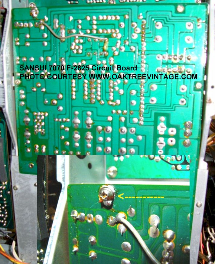
Sansui 7070 Stereo Receiver repair notes;
Issue: On
a recent Sansui 7070 repair / restoration we experienced. The symptoms were
a loud, volume dependant 'pop' noise when most any switch was manipulated,
especially the 'Loudness', the pots, made a 'swishing' sound when turned,
and the tuner was very intermittent (mostly not working). All other inputs
seemed to work. After a bit of investigation, we determined that it seemed
to be associated with the F-2625 circuit board. When we tapped on the board
with a dowel, the tuner would at times start to work. It was appearing to be
most near the Relay, and we have seen corroded relay contacts cause similar
symptoms. Luckily after about 15 minutes of this we discovered it was one of
the screws that secured the board to the chassis, and was supposed to be
soldered in place.
The solder joint had given way and the screw was slightly loose, causing
all the issues. Once tightened (and re-soldered of course), the problem
was solved.
|
Sansui 5000A Stereo Receiver repair notes;
Issue: These receivers are 'cap coupled' outputs. Common
issues are 'aged' electrolytic caps that not always, but sometimes 'have' to
be changed. We recently sank an inordinate amount of time into one of these
(14+ hours) tracking down issues on the 'F-1040' 'driver' circuit board. The
unit was exhibiting a 'slight, intermittent, irregular static' out of one
channel that was independent of any 'source' or 'pre-amp' change /
manipulation after it's basic restore...
Solution that worked for us in this case: We did the normal test for loose
components / bad solder joints which at times did seem to affect it, but we
couldn't narrow anything down. We replaced all the electrolytics, not only
on that board, but the filter caps as well as the coupling caps and the
power supply caps during different stages of it's restoration prior to
concentrating on the 'static' issue. All components on that board were
tested to varying degrees. We finally narrowed it down to a bad, worn-out /
corroded 500k Ohm, pc mounted / micro-pot. However in changing the pot,
something else went south and by that point we were about to 'pull the plug'
on the patient. We did have another Sansui 5000A that had serious FM tuner
issues, but the rest of the unit had been restored. We decided to take a
driver board from it, and move to this unit. Viola, all was well and the
unit 'dialed in' (14 hours later!). Normally we would hope to be into a unit
of that caliber no more than 6 hours. Oh well, you win some, you loose
some...
|
Sansui TR-707AStereo Receiver repair notes;
We've had a customer call to order the 'dial glass' as he said the
'silk-screening' on the reverse side is actually 'water soluble decals'
so be careful when cleaning with any 'water based' cleaners such as 409,
Fantastic, Simple Green, Windex etc. We've actually seen this on vintage Sony
Receivers as well such as the Sony STR-V2, STR-V3, STR-V4, STR-V5 and
STR-4800 and likely others (the part that is "water soluble" is
sandwiched between the front and rear dial glass sheets as they're
'2-layer' assemblies). Of course always be careful with vintage /
antique electronic tubes (valves / bulbs) as well as many of them (Telefunken
and if I remember correctly Amperex Bugle-Boys as well) is / are a prime
example) were silk-screened with 'water soluble' images.
|
|
|
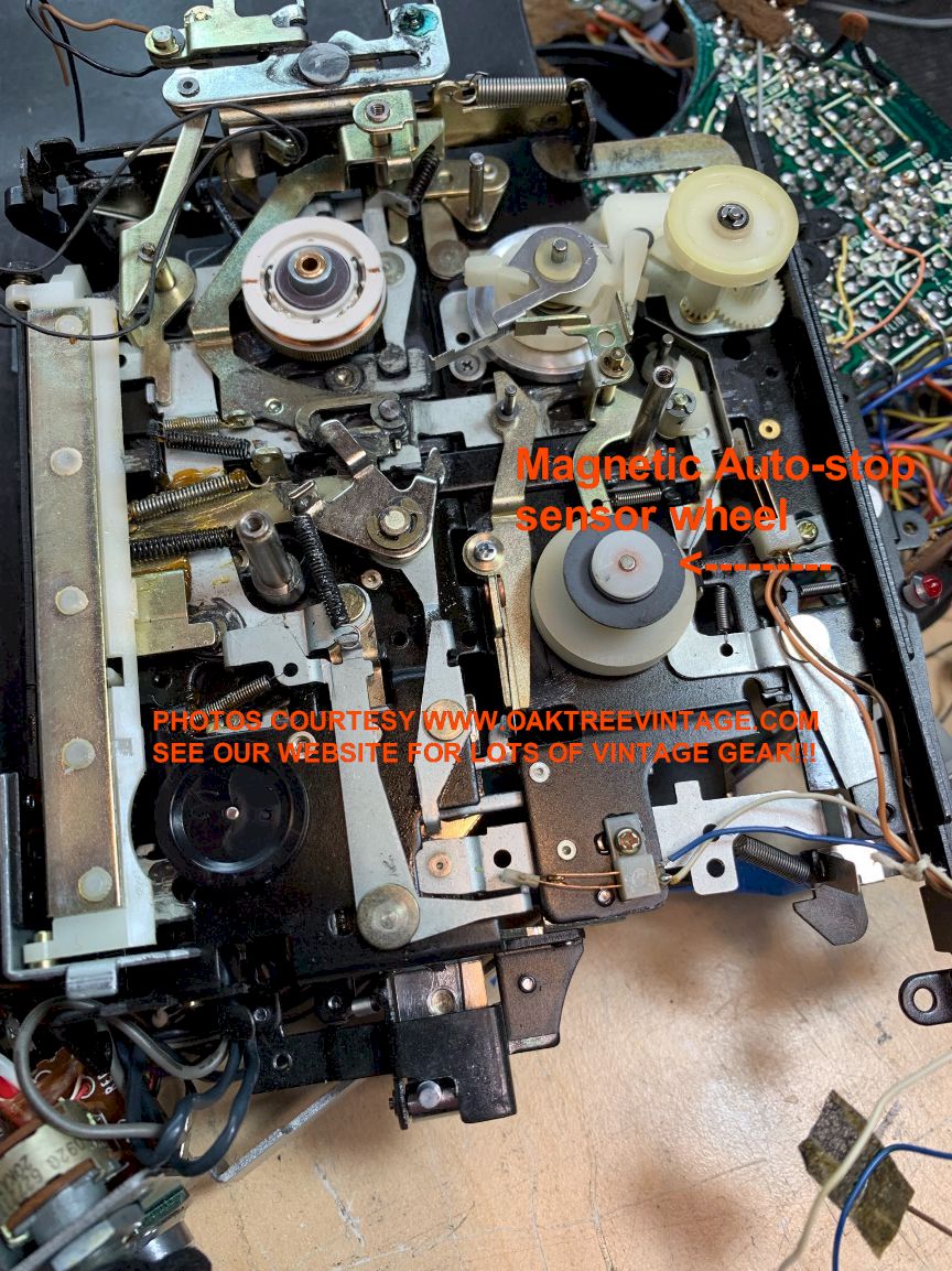
SONY TC-D5M tape had
excessive flutter and could easily be stopped when in playback with the
slightest pressure on the 'supply reel' mechanism inside even following
complete overhaul;
Issue:
We had resurfaced all the tires, and the capstan flywheel rubber and
changed all the belts as well as cleaning all old lube and re-lubing.
This is not only a time consuming process, but this unit is VERY
difficult to work on. It's "packed full" and built in layers.
Internally, there's a lot of point-to-point wiring utilizing VERY small
wires (think tone-arm gauge of wires) (I advise using hot glue to secure
many of the wires to the circuit board and the motor mount to reduce
fatiguing, as YOU WILL break some of them in the process).
Solution that worked for us in this case: After much
prognostication, and MANY HOURS with two technicians involved it was
finally diagnosed to a 'spongy' (but not deteriorating though) pinch
roller. We also looked at changing the pinch roller arm spring, but once
a new pinch roller with a higher 'duro' was installed, the unit 'came to
life' sonically and not only was the flutter tone, but the speed also
increased much closer to exact.
*Another note for technicians. If you are working on the transport with
the circuit board being held vertically (which is pretty much necessary
for any operation on the main transport that is accessed once the
circuit board is hinged out of the way), FF and REW will only function
for a few seconds. There is a magnetic wheel on one of the pulleys, and
a sensor on the circuit board that functions as the 'Auto-Stop' for Fast
Wind. Once the circuit board is lifted up, the sensor cannot read the
magnetic wheel. Stupid design from a servicing standpoint, but it is
what it is.
SONY TC-D5M (note to technicians);
Issue:
If main circuit board is being held 'up', away from it's normal
mounted position, and you are trying to use transport functions, the
tape will only move for a few moments, then shut off.

Solution: Yes, unfortunately that is how it works. There is a
'tape motion / Auto-Stop' sensor mounted to the underneath of the
circuit board that needs to detect motion from a magnetic wheel that
gets turned in the mechanism. If you have the circuit board being held
very far away from the magnetic wheel, the sensor will cut power to the
transport. Adds an extra level of 'fun' to servicing this unit.
|
SONY TC-105 (probably
TC-105A as well) Excessive head wear causing diminished 'high frequency'
playback / recording;
Issue:
Sony TC-105 had diminished high frequency response, especially when
the 'track switch' was set to "1-4". As this is a 'mono' ONLY deck
(4-Track / 1-Channel) we deduced that there were no separate electronics
for the two different positions of the 'Track Select' switch, so there
wasn't much else to cause the issue in the end, other than excessive
head wear (which was fairly visible as well)...
Solution that worked for us in this case: We had 3 Sony TC-200 units (which are stereo) that we thought could have
the same head (and all had other {practically terminal} issues to cause
them to be 'donor units'). Sure enough, they had the same part number,
Sony PP30-4202 LN (however that number is stamped on the 'head housing /
mounting' assembly. You must bend the tabs in the rear and actually
remove the 'head element' which has not identifying marks). We chose the
head that had the least wear of the three, and 'viola', the TC-105 now
played back and recorded high frequency MUCH better and within 6db pole
piece to pole piece. This RPH (Record / Playback Head) head appears to
have been used in at least the Sony models; TC-105, TC-200, TC-250 /
TC-250A, TC-252, TC-255, TC-350, TC-355, TC-530 and likely others. The
coils measure 25 Ohms each.
|
SONY TC-200 Reel to Reel Speed Slow and then runs slower
Issue: Sony TC-250 reel to reel runs
‘slow’ (excessively at about 10% slow, then slows down from there to
about 20% and doesn't stabilize till about 30 seconds each time.) It
will do this every time you stop, then re-start the deck. We've
overhauled EVERYTHING and replaced the start / run capacitors and tried
different motors. This is the 4th or 5th Sony TC-200 that we've
experienced this issue with...
Solution that worked for us in this case: We're still working with them, trying to solve the
problem....
|
SONY TC-350 Reel to Reel Speed Slow issue
(This info would apply to most Sony Reel to Reel tape recorders from mid
1960's thru early 1970's)
Issue: Sony TC-XXX
reel to reel runs ‘slow’. I’ve overhauled EVERYTHING and replaced the
start / run capacitors...
Solution that worked for us in this case: The motor is a ‘Hysteresis’ type motor and its speed
is controlled by the 60Hz cycle of AC power. Originally Sony had optional
and incremental motor drive pulleys available numbered approx -5% thru 0 to
+5% that could be substituted to correct the speed up or down, usually
faster. That could increase the overall speed of the machine. Those are no
longer available and decks usually are going to have the ‘0’ version
installed by default, with no changes having been made throughout their
lifetime. We had a deck that was playing back our 1000Hz test tape at 970Hz.
+/- 3 to about 12 cycles is not too bad / noticeable unless you’re a
musician needing to ‘sync’ tuning with your instrument / voice. 970Hz (30Hz
low in pitch) was VERY noticeable, even with ‘speech’ only tapes and
rendered the deck not usable for playing ‘previously recorded’ tapes.
We ultimately had to take the 100mm flywheel to a
machine shop and have it machined down to 97 mm for our case (we only did
this extreme procedure because we had already invested over 18 hours into
it) and that alone added 3 hours of time running it there and explaining
what was needed and $45 more dollars to the restoration (we tried to DIY it
on our drill press with a vertical file, but it started oscillating /
ringing, which caused the file to ‘chatter’, leaving an uneven surface, not
to mention that the ‘ringing’ sound it made was unbearable in the shop (the
machine shop said the 'ringing' noise was hard on them as well).
|
SONY TC-355 (or Sony Reel decks
with similar hub designs) Loose tape pack on reels issue
Issue:
Sony TC-355 was not packing tape very tightly on the take-up reel
in either direction (FF, REW or Play). Reels spun freely in bushing with
virtually no resistance on the 'Supply' reel, thus tape is very 'loose'
when on the take-up reel. As the reel was spinning so freely (and the
clutches were not in use during these operations) we needed to add some
durable resistance to the reel bearings / axles...
Solution that worked for us in this case: To eliminate 'loose pack' on tape
reels, we lubed both reel table / hub assembly bushings / axles with
300,000 Silicone Gel / Lube. Now which ever reel hub is acting as the
'supply reel, tapes pack properly on both Fast Wind and PB
|
SONY TC-377 / TC-366 Reel to Reel Speed Slow issue
(additional information to the TC-350 issue mentioned above)
Issue:
Sony TC-377 (same transport as TC-366) reel to reel was running
slow, so we had to have the flywheel (2 surface / stepped) machined down
a bit. Once we did that, the clearance from the flywheel to the 'idler
wheel' was too great at the 1 7/8ips setting...
Solution that worked for us in this case: There's not really any official adjustment, so we
had to bend the idler tire connector wire / bar. Not really a fine science,
but 'kinking' it slightly either side of it's spring did the trick.
(photos coming)
|
SONY TC-560 / TC-560D Reel to Reel
intermittent playback / recording of channels (ie; sound cuts out)
Issue: Intermittent sound on playback / record. Sound cut's
out sometimes...
Solution that worked for us in this case: Yeah, this deck has some VERY long, multi-pin switches (I can't remember
exactly, but there's at least 3 that need attention) related to playback
and recording that, while never meant to be serviced, need to be
disassembled completely and cleaned / burnished. They are very 'buried'
between the chassis layers. I may go into a bit of 'how to' at some
point, but suffice to say, it's a VERY difficult and VERY time consuming
process to address this issue on the TC-560 series. Maybe try 'slamming'
the 'play / transport' selector from 'Stop' to 'Play' or aggressively
'jiggle' it to see if that fixes the issue temporarily.
|
SONY TC-580 / TC-730 Reel to Reel.
No specific or 'Red Flag' issues, just a fairly complicated, 'busy' deck
to restore. Lots of things to address, especially since it's capable of
'bi-directional' recording with a centrally located, common pinch roller
(which by the way, we reconditioned twice, but couldn't get rid of
excessive flutter, so ordered a 'Dokorder' pinch roller [virtually
identical roller] out of Europe).
|
Teac A-4010 and it's
variations (Teac A-1000, A-1200, A-1230, A-1250, A-1500, A-1600, A-2000,
A-2300, A-2340, A-3300...Ok, pretty much most or all of the early "A" series
decks...:
The Teac A-4010 / 4010S
etc, was probably 'the most sold' reel to reel deck ever made by anyone.
Seems like pretty much everyone that went to Viet Nam during the war came back with one of
these. They are fairly typical of most reel to reel restorations (plan on
15-20+ hours to do a thorough job), but they have one unique mechanism that
will certainly need to be addressed. It's the pinch roller arm assembly
(#14142 {aka; 50141420} on the A-1200, A-1200U, A-4010, A-4010S). It
is a 'cast / pot metal' affair that pivots on a pin / axel. The pin
may be detachable from the main chassis or can be riveted / 'press-fit'
/ braded in-place.
Either way, the arm will be in some state of 'sluggishness' to
completely 'frozen' due to old,
varnished lubes. It will need to be removed, cleaned and re-lubed. It
may need to be heated (best with a heat gun or blow dryer) to facilitate removal. Do not force it, or you may
loosen the press fit pin yes, I've done that by not waiting long enough
for the heat to take effect). Wait for the 'heat' to take effect, then with a
suitable tool (pliers) wriggle / twist it back and forth as you pull up on the
pinch roller arm. You may need to re-apply heat during the process until it's
completely free of the pin. Once done, the bushing / pin surfaces can be cleaned
with solvent and properly re-lubed (along with pretty much every other moving,
mechanical part in the deck).
|
Teac A-6010GSL and it's
variations: Issue: The tape tends to 'track off' or skew out from
the pinch roller / capstan on my reel to reel tape deck...
Likely applicable
to most TEAC's around this model / generation...
Solution that worked for us in this case: While many tend to blame the 'pinch roller' or bent or skewed tape
guides, I have usually found this to be the fault of improper 'back
tension' on the supply reel and on a couple of occasions, too little
pinch roller pressure. You can test that theory by applying a bit
of 'caliper braking' action to the outside edge of the supply reel with
your fingers while the deck is playing. Not much, just a bit, and the
tape will usually come back into alignment. Unfortunately, this is not
usually an easy thing to correct. On earlier decks, such as Sony's, it's
done with a clutch made of felt, on others, with brake pads. On later
decks, it's typically done with a small amount of 'reverse' voltage
applied to the 'supply reel motor'.
If the back tension is 'maxed', you can still affect it
with adding pressure with your fingers, then it's likely lack of 'pinch
roller' pressure. You can test this theory, by adding pressure to the
pinch roller, towards the capstan. If you're able to do it quickly
enough when you see the tape 'start' to skew, and the added pressure
pulls the tape back to the correct path, then you've probably determined
the problem. Some decks may let you adjust pinch roller pressure, some
may not.
Regardless, any of the measures to
address the 'tape skewing' symptom, any repair is not particularly 'end
user friendly' is beyond the scope of this page.
Seek professional assistance for that one.
(revised 2019)
|
Teac A-6300 can't find
'specified input levels' in service manual to build remainder of
calibration / adjustments on:
May be applicable
to most TEAC's around this model / generation...
Solution that worked for us in this case: Our tech spent quite a lot of time trying to do a 'work around'
regarding this, and I suggested he check some the service manuals from
some other contemporary units. The first alternative manual he checked
was for the TEAC A-2340R and it had the missing "Specified input level"
information on page 21 of the manual.
(revised 2021)
|
Teac 3440 Auto-Stop doesn't
work, but 'Stop' button works fine;
While this could be an issue with the 'transport / Logic'
circuit, it's likely an issue with the 'micro-switch' that the tension arms
control. The switch could be bad / broken, or may need to be adjusted
slightly in it's mounting. We have seen the mounting bracket need to be
're-built'. This problem / solution would be applicable to many brands /
models of reel to reel tape decks.
Teac 3440 Channel playback doesn't work on all channels or is
intermittent;
While there are a
number of possible suspects, one of the main failure points on a TEAC
3440 are the circuit board / card 'edge connectors'. The contacts likely
need to be cleaned / burnished, and / or the contact 'fingers' need to
be 're-sprung'.
Teac 3440 Meter lamp is out and I can't figure out how to access them to
replace;
Oooohh Boyieee! Have fun
with this one. For what would seem like what should be a
'simple thing' to rectify, you'll find out that it's not. While most of them
are accessible via normal means / efforts, the bulbs / lamps on meter #
4 will require a substantial disassembly of the deck to address. Accessing them is
half the battle, and it's going to be a fairly long battle. Pretty much most
of the deck will need to be disassembled (not very forward thinking on TEAC
/ Tascam's part from a 'serviceability' standpoint) to access the meters
(TEAC / Tascam fixed this and most of the other 'serviceability' issues on
the later TEAC 40-4 (waayyy better deck) ). Once there, you'll need to make
sure that what ever lamps / bulbs / LED's you choose have a very low current
draw collectively (like less than 100mA). If you exceed the current draw
limits, an 'Output Muting' circuit will cause the output from the playback
amp to cease. I don't remember at this point what the current 'threshold'
is, but it's pretty low. We replace with LED's so the cumulative current
draw is VERY low relative to incandescent counterparts (and 'incandescent'
lamps / bulbs that work on 7.5 Volts, and draw 20-30 mA are very elusive to
obtain in any 'physical package' we've found )
|
Teac V-95RX Service Manual
misprint in the "Electrical Checks and Adjustments" section;
In the section regarding adjustment of internal levels in the service
manual for the TEAC V-90RX / V-95RX; Any reference on page 13 that
specify: "400HZ / -9dB (436mV)" SHOULD READ "400HZ / -5dB
(436mV)". This misprint caused us many hours of frustration / tech co$t!
(This appears to have been corrected in subsequent model service
manuals).
|
Teac V-95RX (also TEAC
V-90R and likely others) Hub brake rubber gooey which can cause the
issues listed below in the next topic. Also may not properly 'brake' the
reel hubs, thus allowing tape to free-wheel off / get slack;
We recently restored three of TEAC V-95RX cassette decks.
We discovered that the entire 'head sled / braking' mechanism had the
same old, stiff grease that the other models similar to this. The sled
had to be removed, the old lube 'solvent cleaned' and re-lubed. This one
also had an additional issue. The rubber brake pads were deteriorating
(reverting back to their natural, 'gooey' state due to the way they were
originally vulcanized) and not only were not contacting the reel hubs
anymore (means NO brakes), but their 'gooeyness' had migrated to the
'sled track' and was causing the sled to be additionally sluggish. New
rubber brake pads were fabricated
out of some rubber
sheeting we had here at the shop
and fitted.
They were then (fastened in
place with super glue as most rubber is very receptive to cyanoacrylate
glue). This was a BIG, time consuming and unexpected operation that had
to be done.
|
Teac V-95RX (also TEAC
V-90R and likely others) Excessive flutter;
We had already tried different main flywheel belts, and even installed a
new pinch roller on once side (the 'reverse' side was the one at issue).
We finally discovered that the flutter would disappear if upward
pressure was added to the pinch roller arm (thus increasing it's contact
pressure with the capstan(s)). This isn't readily adjustable, so the
only way to address it was to increase the spring tension to springs;
5800357600 and 5800357800 by forcibly 'un-coiling' them almost 1
revolution which added many degrees of additional tension to the pinch
roller arm.
|
|
|
Teac V-909RX Random /
Intermittent Buzz / noise / clicks / pops;
The first thing I think about causing this would be a bad ground,
although there are a myriad of possible causes; 'barely hanging on'
wire, loose connectors, intermittent / bad / cold solder joints,
intermittent component lead / body junctions and the like. We noticed
when we flexed the entire chassis (with the cover / bonnet off) the
noise would come and go with the deck in 'play' mode. After much time
flexing circuit boards, disconnecting circuit boards, removing the
transport (to isolate it), trying to isolate functions, we finally
located a 'ground screw' on the rear, left of the power supply circuit
board (had to lift the transport control circuit board) to see it. Once
we had access to it, I immediately saw the ground screw and tapped on
it. We removed the screw to further determine it was the issue and once
we were sure, replaced and tightened it. Problem solved. The screw was
actually fairly snug, and the solder pad looked shiny, but was not
getting a sufficient connection.
|
Teac X-1000R Meter lamp current draw;
Do not substitute higher than intended current draw light
bulbs in the meter. We installed 250mA lamps and the logic circuit failed.
We removed them, and it worked again. We then modified some 35mA lamps to
fit and they worked well with the unit. The same may be applicable to the
Teac X-2000R as well, but that's only an assumption.
|
Technics SA-104 receiver model and likely others,
Potentiometers / controls;
We have twice seen the wipers inside the treble pots detach from the
internal, rotating disc. On this particular pot, there are 6 solder
terminals (as well as 2x anchor solder points) and approx 8-10 "fingers"
between two separate wipers. The "wipers" are held to a rotating plastic
disc with 'melted plastic' thru holes in them. The plastic that is
'mushroomed' up thru the holes in the thin wiper metal can give way,
allowing the metal wipers to float freely inside the potentiometer
housing. With further manipulation of the pot shaft, damage to the
fragile wiper fingers can happen, thus almost certainly causing
irreversible damage to the pot. Any replacement from another unit, may
suffer the same fate. Proactively 'melting' more plastic thru the holes
with a soldering iron of each wiper could address this. We have actually
done this with what appeared to be decent success. Time will tell.
|
Technics SA-600, SA-700, SA-700A receiver models and likely others, DIAL /
METER LAMPS;
The original / OEM lamp / bulb utilized in this
receiver was a Stanley 6.3V / 250mA, #XAMR62S. While this bulb did
originally tend to have a typical and sufficient lifespan, we have found
that the new 250mA bulbs available (as the original Stanley XAMR62S does not
appear to be available anymore) are not of the quality of the ones that were
originally available, and will not last very long (likely less than 30 days
of normal use). The 250's are burning extremely 'white hot', which will look
good for a while, but again, what's available today are not as robust as the
originals. Trying a #1302, 6.3V / 40mA is a bit too dim, but 6.3V / 150mA,
#1847, is a good compromise. Still not as bright / hot as the original 250mA
lamps, but work well, and illuminate the front panel sufficiently.
|
Technics SB-7000 / SB-7070 Speaker Foam Surrounds;
There seems to be a general opinion out there
that the foam woofer surrounds on Technics SB-7000's and SB-7070's are
'special' and do not rot or require replacement. B-o-o-o-o-o-o-gus!
While the do often appear to be in better shape / condition than the foam
surrounds on most drivers, and do not seem 'as rotted' or deteriorated, they
do deteriorate and will crack. A seemingly perfect appearing pair, will
start releasing after a few 'loud' selections from a 'stout' amplifier. The
same is all applicable to Radio Shack, 'Mach Ones' woofer foam surrounds.
Both the Technics SB-7000's and SB-7070's and the Radio Shack, 'Mach Ones'
did come with some very 'durable' foam surrounds, that will appear at first
to "still be serviceable" and / or "don't need surrounds", but they are not
immune to foam rot. Unfortunately, there aren't any 'exact fitting' foam
surrounds available for the Technics SB-7000's and SB-7070's so you need to
get a kit that is close and 'sever and splice' it (not a big deal, nor
detrimental) to resurrect them. Try www.speakerrepair.com ,
www.partsexpress.com or
www.simplyspeakers.com to name a few.
|
Technics RS-1700 / RS-1500
/ RS-1520, RS-1506US:
These are difficult machines to address all the systems that will likely
need to be service. They're brakes are fairly weak by design (Like my
Chevy 2500 Duramax and my GMC Workhorse Class-A RV chassis), so some
modifications will likely need to be made and extensively tested to make
them more usable. Also they have multiple 'Air-Bellows' inside to dampen
the motion of the tape tension arms. Quite 'un-orthodox' and will again,
require extensive testing to get them to a utilitarian level of
function. Also, there's a LOT in internal level adjustments that likely
need to be made.
Additionally, the Service Manual for the Technics RS-1700 is of little
use for carrying out many of the internal, electrical adjustments. The
Technics RS-1520 service manual was also of not help, however the
service manual for the Technics RS-1500US manual did have detailed
information on the electrical adjustment which were applicable to the
Technics RS-1700.
Noisy Tape / Source Toggle switches. Normal cleaning
with contact cleaner doesn't help. The metal has a high silver content
in it, so it simply 'tarnishes'. Contact cleaner doesn't remove tarnish
sufficiently to address noise.
The toggle switches will need to be disassembled, have their contacts
burnished, then solvent cleaned and re-assembled. This is not something
that was ever meant to be done, but due to the scarcity of replacements,
"ya gotta do what ya gotta do". They can be de-soldered and removed from
the cb, without taking the entire front, sheet metal, chassis off. Once
removed, there are six tabs to bend straight to remove the guts. Once
removed the tracks / rails need to be burnished (a fiberglass pen is
best for this, but you could use some fine 'Scotchbrite' as well). The
moving contacts need to be burnished with some 1000-1200 grit (or
something similar) wet/dry paper. I would also give them a slight
'squish' to "re-spring" their grip. One done, then wash with solvent
cleaner either prior to or after assembly. Once re-installed, they
should be MUCH quieter.
|
Yamaha CR-820 receiver intermittent sound:
Issue: We had a Yamaha CR-820,
that had an issue with intermittent sound (don't remember the particulars of
which channel) that was taking an inordinate amount of time to
trouble-shoot. Acted like a bad / cold solder joint, broken trace etc,
however we couldn't track it down to any particular area of the unit or
circuit board. Seemed like anywhere we 'taped' or banged on it, we could
affect it...
Solution that worked for us in this case: After about 2 hours, we discovered that one of the circuit board
mounting screws was designed to ground that board to a part of the chassis
that ran down the middle of the unit. A quarter turn of the screw and the
problem went away. We have since had a similar issue with a Sansui 9090DB
and a JVC JR-S501 receiver.
|
Yamaha CR-2020 receiver...power
supply circuit board issues:
Issue: We had a Yamaha CR-2020,
that had an issue with intermittent issues...
Solution that worked for us in this case: We traced it down to multiple
issues with the power supply board. We also discovered in originally
doing the refurb / service on it that there were at least 2 or 3
'service bulletins' that had been released on this unit regarding
upgrading some of the parts on the power supply circuit board. Even
still, it had run hot in the past, which had caused 'browning' of the
board and some traces to lift. Also, part of the work dictated by the
service bulletins involved installing 'heavier' (higher mass) resistors,
which now put extra stress on the solder joints. We also found that the
heat sinks on the voltage regulators were secured to the board only by
the soldered leads of the regulators. We're in the process of utilizing
'high temp' epoxy to secure the parts and patch up the solder joints /
traces.
|
Yamaha 'M-40 / M-60 / M-65 / M-80 / M-85 / MX-1000 / MX-1000U' Speaker
output posts prone to breakage, especially in shipping / transit:
Issue:
We have learned the
'hard way' not to ship a Yamaha 'M-Series' amplifier without removing the
'Red' and 'Black' speaker connectors from their binding posts...
Solution that worked for us in this case: In fact, it's
probably best, if possible, to remove the 6 philips screws and push the
entire barrier strip back into the back panel (add a bit of 'easily
removable' packing to reduce 'rattle' in transit).. On the Yamaha M-60 power
amp, it's at least possible. The Yamaha 'M-80' may not be as conducive to
this procedure, but AT LEAST, remove the Red and Black posts. To further
reduce the chance of future 'handling' damage, we also 'shot' the underside
of the plastic housing (the part that breaks) full of 'hot glue'. That adds
A LOT of structural integrity to the assembly. We are VERY good at packing,
with only ONE (1) minor ship damage issue in over 18 years / 19,000+ packs.
That's an INCREDIBLY UNBELIEVABLE record!!! Ironically, this amp was damaged
utilizing the ORIGINAL YAMAHA M-60 FACTORY BOX AND PACKING, that was in turn
'floated' in an oversize box with more packing. I used to sell this amp new,
as a dealer, and I don't remember the speaker post inserts being removed for
shipment, but could be mistaken. Regardless, we will from now on.
|
Yamaha R-1000 receiver - add to 'No Fly' list:
We have just tried to
restore our last Yamaha R-1000. These seem to always have issues with a
Darlington pack STK3106 'Driver power pack'. Hard to find, difficult to
troubleshoot and short of replacing it, nothing to repair. Also, unit use a
proprietary battery for the FM tuner preset memory. Not a 'big' issue, as we
can 'special order' them, but coupled with the STK3106 issue, it's just not
one of the better unit to sink much time into.
|
|
MISC NOTES:
A bad ground, corroded / fatigued wire or cold solder
joint can chew-up 'HOURS' of tech time trying to find and can be very
exacerbating, both for the tech and the person paying the bill. Generally
other than 'hunting and pecking' or reflowing EVERY solder joint, it / they
can be difficult to locate.
Hi Dominick,
Thanks again for visiting oaktreevintage.com.
Most of those symptoms you described could likely be attributed to
‘noisy transistors’ (not sure about the proximity of your hand thing
though), which in the case of these units could certainly be from “black
legged” transistors. It’s easy enough to look at your board and see if
yours have black leads (all four of the “A726” transistors in the middle
of mine have black legs). Changing them would be my first step. Mine may
or may not work at this point, but with transistors that are prone to
“black legs”, it’s not a matter of “if”, but “when”. Having "black legs"
on devices doesn't mean that the device is bad (yet) so if yours are all
still functioning properly, changing them may not address your symptoms
(but again, it's a good bet they're causing some if not all the
symptoms). While you’re at it I would change out the six electrolytic
capacitors on the board as well (although they’re less likely to be
causing any issues contrary to what you read all over the interwebs).
Thanks again, Jerry at www.oaktreevintage.com (800)-806-4231 option “2”
Mtn Time 10AM-6PM
Issue
via email:
Hello, I want to know if you
have this driver board (Sansui F-1499) and if
so what is the condition of the part and how much is it. Also, include
S&H fees....
Responses:
"Hi Dominick,
Thanks for visiting www.oaktreevintage.com .
A couple of questions first:
- Are you the tech on this Sansui 771?
- What is wrong with the current F-1499 driver board in the unit?
Our donor board may / will likely have (as stated on our all our parts
pages), “black legged devices”, certainly 40-60 yo capacitors, resistors
that may have drifted etc. The board will have good traces and be crack
free, AND at the time it was parted out was taken out of a unit whose
amp worked fine, just had ‘tuner’ issues, but parts age simply sitting
in a drawer. If any of the above are the reasons you’re needing a
replacement, then I would simply replace the components on your board.
If your board is cracked, burned, deteriorated for some other reason,
then my board would be the next step.
Just let me know the answers to the above questions. Regards,
Jerry at www.oaktreevintage.com"
--------------
"Hi Dominick,
Thanks again for visiting oaktreevintage.com.
Most of those symptoms you described could likely be attributed to
‘noisy transistors’ (not sure about the proximity of your hand thing
though), which in the case of these units could certainly be from “black
legged” transistors. It’s easy enough to look at your board and see if
yours have black leads (all four of the “A726” transistors in the middle
of mine have black legs). Changing them would be my first step. Mine may
or may not work at this point, but with transistors that are prone to
“black legs”, it’s not a matter of “if”, but “when”. Having "black legs"
on devices doesn't mean that the device is bad (yet) so if yours are all
still functioning properly, changing them may not address your symptoms
(but again, it's a good bet they're causing some if not all the
symptoms). While you’re at it I would change out the six electrolytic
capacitors on the board as well (although they’re less likely to be
causing any issues contrary to what you read all over the interwebs).
Thanks again, Jerry at www.oaktreevintage.com (800)-806-4231 option “2”
Mtn Time 10AM-6PM"
---------------
"Hi ,
Thanks for visiting oaktreevintage.com. Most of those symptoms you
described could likely be attributed to ‘noisy transistors’, which in
the case of these units could certainly be from “black legged”
transistors. It’s easy enough to look at your board and see if yours
have black leads (all four of the “A726” transistors in the middle of
mine have black legs). Changing them would be my first step. Mine may or
may not work at this point, but with transistors that are prone to
“black legs”, it’s not a matter of “if”, but “when”. While you’re at it
I would change out the six electrolytic capacitors on the board as well
(although they’re less likely to be causing many
issues contrary to what you read all over the interwebs
{so far}). Thanks again, Jerry at www.oaktreevintage.com"
|
Units / topics we will be addressing
in the future:
Kenwood 'Eleven-III' & KR-9600 'push-button' keeper issue, and don't
remove from front.
Pioneer SX-3700, SX-3800 & SX-3900 dial light change difficulty.
|
NO OTHER INFORMATION, NOR ASSISTANCE AVAILABLE
PLEASE DO NOT CONTACT US WITH QUESTIONS SUCH AS, "HOW DO I.....? OR "HOW DO
YOU REPAIR A.....?"
We do not have the resources to address any repair / DIY questions.
|
-
ATTENTION: We recommend you DO NOT DISASSEMBLE or ATTEMPT TO REPAIR OR
REPLACE ANY PARTS ON ANY ELECTRONIC / ELECTRICAL DEVICE without proper,
technical training and repairs / modifications should always be left to
qualified technicians.
"WARNING: PLEASE
USE CAUTION WITH ANY ELECTRICAL DEVICE. ANY REPAIR AND / OR RESTORATION
SHOULD BE UNDERTAKEN ONLY BY A QUALIFIED TECHNICIAN. DO NOT OPEN OR ATTEMPT
TO REPAIR ANY ELECTRONIC DEVICE WITHOUT PROPER INSTRUCTION, EXPERIENCE,
BACKGROUND, TRAINING OR KNOWLEDGE, OR TAKING PROPER SAFETY PRECAUTIONS.
THERE ARE NO 'USER SERVICEABLE' PARTS, SYSTEMS OR CIRCUITS INSIDE.
POTENTIALLY HARMFUL, INJURIOUS AND / OR LETHAL ELECTRIC VOLTAGE AND CURRENT
INSIDE.
IT CAN KILL YOU AND WILL HURT THE ENTIRE TIME YOU ARE DYING"
|